Descrizione
SAGEM control unit for PEUGEOT 206 1.4i vehicles
Part description
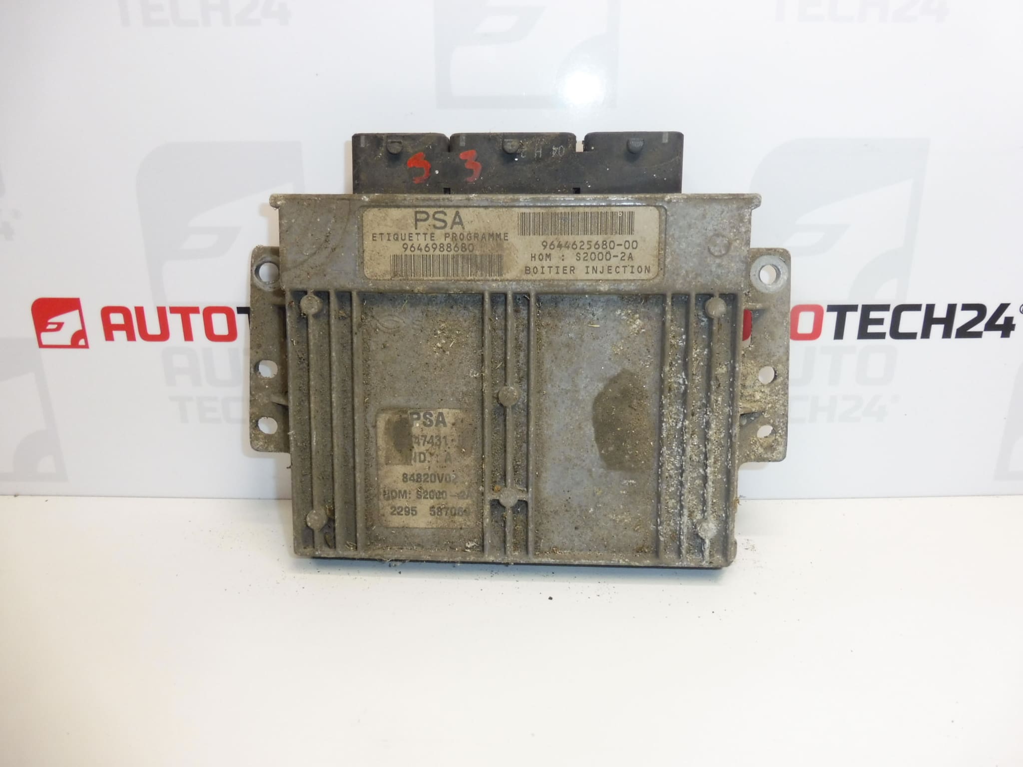
Used Sagem S2000-2A fuel injection control unit for Peugeot 206 1.4i. It controls fuel injection and related engine functions based on sensor signals. It is a suitable option for replacing a faulty unit if it matches the required specification and is correctly adapted to the vehicle.
When selecting a unit, compare in particular the S2000-2A designation and product numbers 9644625680, 9646988680 and 1940W1 with the original unit. A match with the vehicle model alone is not enough to confirm interchangeability. A used control unit may also require data transfer or coding; simply connecting the plugs may not allow the engine to start.
Technical information
- Manufacturer: SAGEM
- Model: Peugeot 206
- Engine specification listed in the source information: 1.4i
- Unit type: S2000-2A
- Part category: fuel injection control unit
- Condition: used part
- Additional number: 1940W2
- Additional designation in the source information: NFP
Product codes
- Product codes: 9644625680, 9646988680, 1940W1, 1940W2
- Type designation: Sagem S2000-2A
The codes listed make it easier to identify the part and compare it with the original unit. Their presence alone does not confirm interchangeability across all hardware and software variants.
Installation recommendations
The following applies generally to this type of part: replacing a fuel injection control unit involves both mechanical installation and electronic adaptation. The steps below are general; the exact procedure, power disconnection, and programming method depend on the specific vehicle and unit configuration.
1) Before installation
- Use diagnostic equipment to verify the cause of the fault. A problem with the power supply, grounding, wiring, or connected components can mimic a control unit failure.
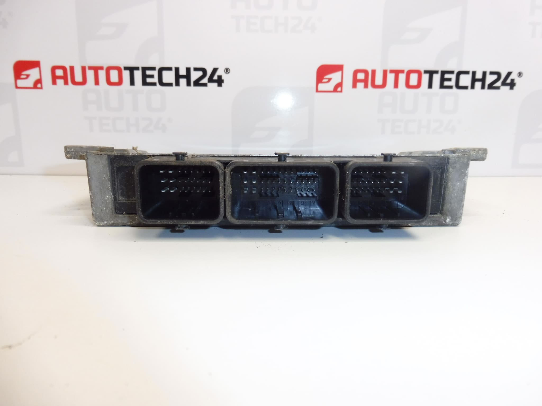
- Compare the product numbers, type designation, connectors, mounting points, and available hardware and software version information with the old unit.
- Inspect the used unit: the casing, contacts, and connector locks must show no obvious damage, moisture, or corrosion.
- Determine the data transfer or initialization method in advance. If the original unit communicates, back up the available data and configuration.
2) Required tools and materials
- Standard hand tools suitable for the mounting hardware and tools for safely releasing the connectors.
- PSA diagnostic equipment and, depending on the procedure selected, suitable programming equipment.
- A multimeter for checking electrical circuits in accordance with the service documentation.
- Products suitable for cleaning electrical contacts, clean work supplies, and electrostatic discharge protection when working with electronics.
- A regulated power supply suitable for programming and meeting the requirements of the service equipment used.
3) Step-by-step installation procedure
- Record the symptoms of the fault and read the available diagnostic data before disconnecting the unit.
- Check the power supply, grounding, and related wiring. Correct the cause of any damage before connecting the replacement part.
- Back up the original unit’s data, if it can be read safely, and prepare the selected method for commissioning the unit.
- Switch off the ignition, allow the electronic systems to enter their inactive state, and disconnect the battery according to the vehicle manufacturer’s procedure.
- Access the unit according to the service documentation. Clean the area around the connectors before disconnecting them to prevent dirt from entering.
- Release the connector locks and disconnect the connectors without pulling on the wires or levering against the contacts.
- Release the mountings and remove the original unit. Check the brackets, wiring harness, and for any signs of water ingress.
- Compare the two units again. Have the cloning or preparation for initialization carried out professionally according to the selected procedure.
- Secure the replacement unit without putting strain on the casing or wiring. Fit the connectors in the correct position and secure their locks.
- Reconnect the battery according to the manufacturer’s instructions. If required by the selected method, carry out initialization, telecoding, and key adaptation using the prescribed equipment and a stable power supply.
- Verify diagnostic communication, correct configuration, and whether the engine can be started. Assess any faults before the test drive.
4) Post-installation checks and test drive / function verification
- Verify that the engine starts, runs steadily, and responds to throttle input.
- Check the warning lights and diagnostic data. Clear the fault memory only after recording the faults and addressing their causes.
- If the engine runs correctly and the vehicle shows no faults that could compromise safety, take a short test drive and then run a diagnostic scan.
- After verifying operation, check that the connectors are secure and the wiring is routed correctly.
5) Common installation errors and how to avoid them
- Replacing the unit without verifying the original fault: first check the electrical circuits and connected components to prevent the replacement unit from being damaged again.
- Selecting a unit based only on the vehicle model: also compare the unit designation and available information about its specification.
- Connecting the unit without the necessary adaptation: prepare for cloning or initialization and key adaptation before installation.
- Forcing the connectors and damaging them: always release their locking mechanism first.
- Interrupting the power supply during programming: use suitable power support and do not interrupt an ongoing write operation.
- Leaving moisture or corrosion in place: address not only the resulting damage, but also its cause.
Installation and coding – important
- The unit is used and is “paired” with the original vehicle (VIN/PIN/keys).
- Commissioning options:
- Cloning data from the old unit (EEPROM/Flash) – after cloning, the unit is plug and play.
- Virginization followed by initialization/telecoding via DiagBox (possibly online) + key adaptation.
- It is recommended that the work be carried out by a professional with PSA service equipment (DiagBox/Lexia/PP2000).
- Always disconnect the battery before removal/installation and follow the manufacturer’s procedure to prevent damage to the unit.
Reasons why the part may be damaged
The following causes can generally lead to damage to fuel injection control units. This is not a description of the condition found on this particular unit.
- Moisture and corrosion on the contacts or inside the unit.
- A short circuit in the wiring or a connected component, which can damage the output circuits.
- Overvoltage, incorrect polarity, or improper work on the power supply.
- Thermal stress, vibration, and ageing of electronic components.
- Improperly opening the unit or interrupting programming, which can damage the electronics or prevent the unit from functioning.
Eliminating the cause of the original fault before replacement helps protect the replacement unit and prevent repeat repairs.