Descrizione
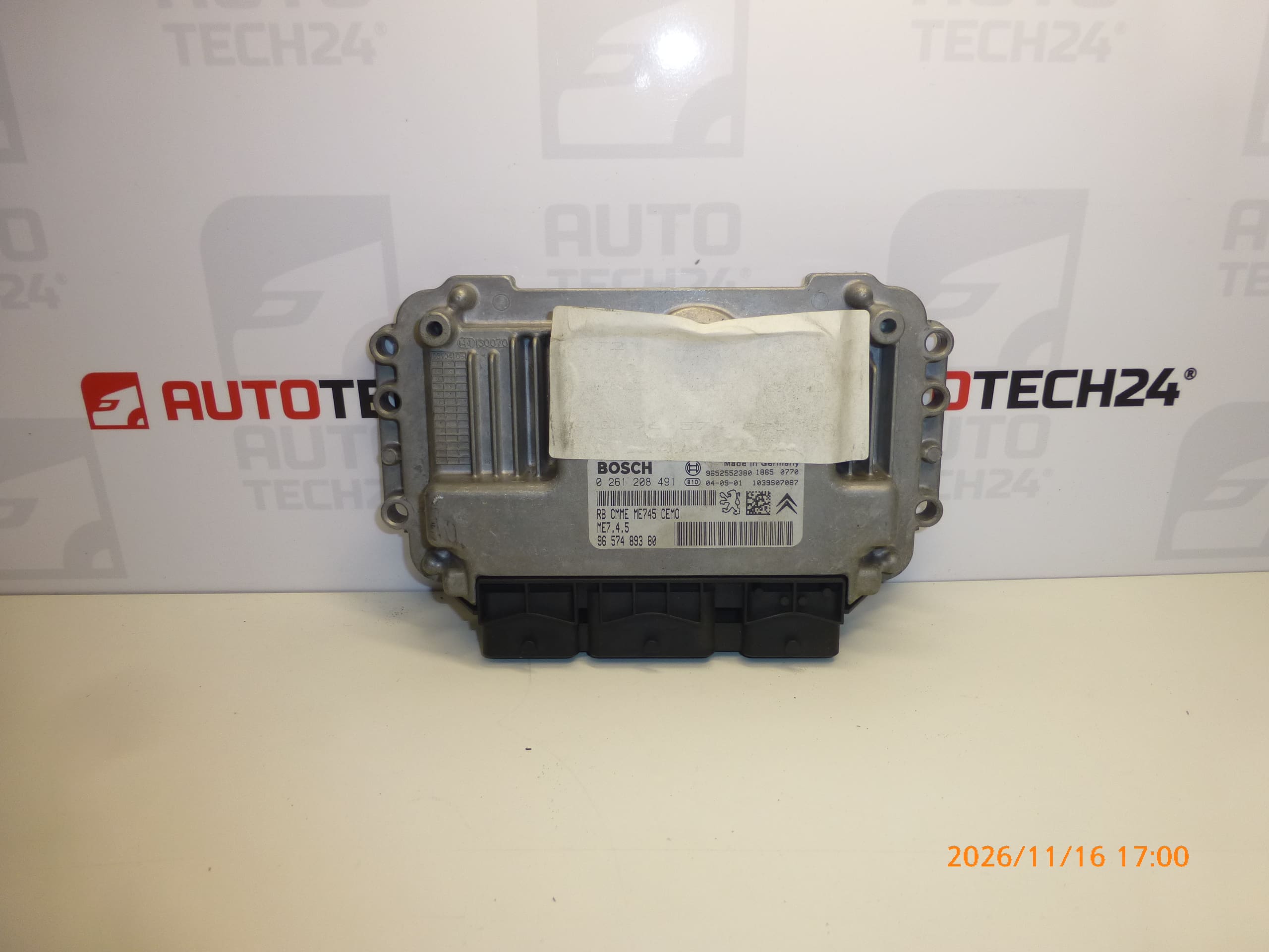
BOSCH ME7.4.5 engine control unit for CITROEN C4 1.6 16V vehicles
Part description
Used Bosch ME7.4.5 engine control unit for the Citroën C4 1.6 16V controls fuel injection and other engine operating functions. When replacing a faulty unit, the key identifiers are 0261208491, 9657489380 and 1940SV, along with the matching version and correct adaptation of the electronics to the vehicle.
This is a repair solution for a vehicle with a matching unit, intended for auto repair shops and technically experienced owners. A used unit cannot be considered ready for operation simply by connecting the connectors – replacement requires data transfer or coding as described below.
Technical information
- Manufacturer: Bosch
- Model: Citroën C4
- Engine specification listed in the source materials: 1.6 16V
- Unit type: ME7.4.5
- Part category: engine control unit / fuel injection
- Condition: used part
- Additional numbers: 9652552380
- Additional designation in the source materials: NFP
Product codes
- Product codes: 0261208491, 9657489380, 1940SV, 9652552380
- Type designation: Bosch ME7.4.5
- Model: Citroën C4
When selecting a unit, compare the numbers and type designation with the existing unit. A matching model name alone is no substitute for comparing the unit version and its programming requirements.
Installation recommendations
The following procedure is a general guide to replacing an engine control unit. The exact removal, power disconnection and programming steps depend on the specific vehicle version and the manufacturer’s service instructions.
1) Before installation
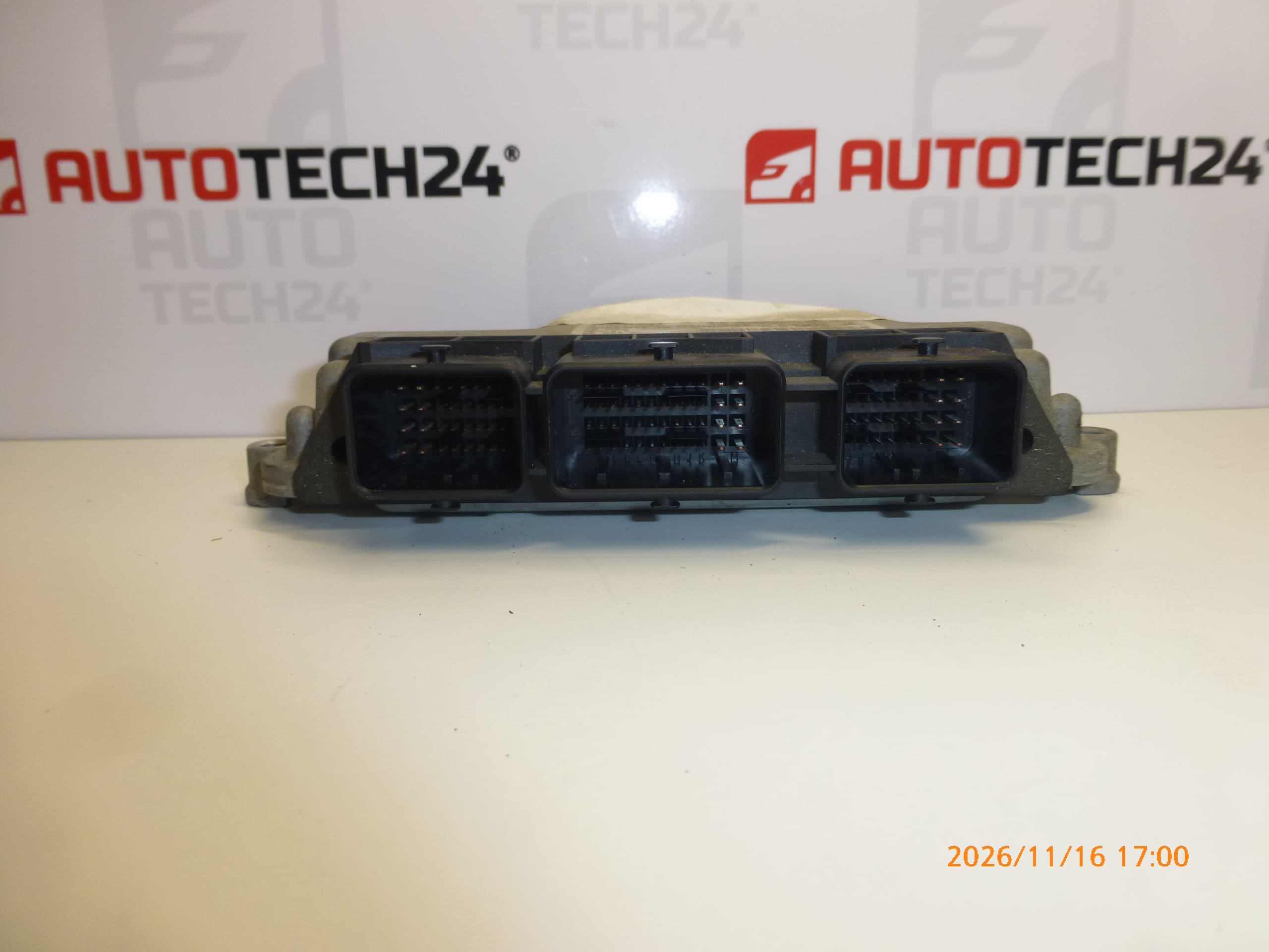
- Compare the Bosch ME7.4.5 designation, product numbers, connectors and mounting points with the original unit.
- Inspect the housing, connector cavities and contacts. Pay particular attention to cracks, oxidation, signs of moisture, overheating or previous intervention.
- Use diagnostics and inspect the wiring to verify the cause of the fault. A power supply, ground or wiring fault can mimic a faulty unit and may also endanger the replacement unit.
- Choose the data transfer or initialization method in advance. Keep the original unit available for possible cloning.
2) Tools and materials required
- Standard hand tools suitable for the unit’s mounting and access requirements.
- Diagnostic equipment suitable for the vehicle and professional programming equipment for the selected commissioning method.
- A multimeter for checking the power supply and electrical connections.
- Tools for labeling connectors and suitable products for gently cleaning electrical contacts, if cleaning is required.
- A suitable power supply stabilizer for programming, in accordance with the requirements of the service procedure being used.
3) Step-by-step installation procedure
- Perform an initial diagnostic scan and record the available information about the original unit, faults and configuration.
- Check the power supply, ground and related wiring. Rectify any faults found before connecting the replacement unit.
- Agree on the commissioning method with a specialist and arrange a backup of the original unit’s data, if it can be read.
- Switch off the ignition, allow the electronics to enter standby mode according to the manufacturer’s instructions, and disconnect the battery using the prescribed procedure.
- Access the unit according to the service documentation for the specific vehicle; remove only the parts that are necessary to gain access.
- Label the connections as needed, release the connector locks and disconnect the connectors without pulling on the wires.
- Release the mounting and remove the original unit. Inspect the area around its mounting point for signs of moisture or damage.
- Compare the two units again and have the data cloned or the unit prepared for subsequent initialization, depending on the selected method.
- Fit the replacement unit into the bracket and secure it according to the manufacturer’s instructions. The wiring must not be stretched or pinched.
- Connect the connectors and check that their locks are fully engaged. Reinstall any protective and access panels that were removed.
- Reconnect the battery according to the manufacturer’s procedure and perform the required initialization, telecoding and key adaptation according to the selected method. Ensure a stable power supply during programming.
- Perform a final diagnostic scan and verify starting and engine operation. Resolve any remaining faults before a test drive.
4) Post-installation checks and test drive / functional verification
- Verify communication with the unit, correct key recognition and the ability to start the vehicle.
- Check engine operation, response to the accelerator pedal and any warning lights.
- If the vehicle has no faults that would prevent safe operation, take a short test drive and then read the diagnostic codes again.
- After verifying operation, check that the unit is secure and the connectors are locked in place.
5) Common installation mistakes and how to avoid them
- Replacing the unit without verifying the cause of the fault: first check the power supply, ground and wiring.
- Selecting a unit based only on the vehicle model: compare the product numbers, unit type and version.
- Failing to pair the unit with the vehicle: prepare for data transfer or initialization before carrying out the replacement.
- Disconnecting connectors by force: release the locking mechanism first and do not pull on the wires.
- Power interruption during programming: follow the programming equipment requirements and ensure a stable power supply.
- Failure to address water ingress or wiring damage: eliminate the source of the problem to prevent the fault from recurring.
Installation and coding – important
- The unit is used and is “paired” with the original vehicle (VIN/PIN/keys).
- Commissioning options:
- Cloning data from the old unit (EEPROM/Flash) – after cloning, the unit is plug and play.
- Virginization followed by initialization/telecoding via DiagBox (possibly online) + key adaptation.
- It is recommended that this be carried out by a specialist using PSA service equipment (DiagBox/Lexia/PP2000).
- Always disconnect the battery before removing or installing the unit and follow the manufacturer’s procedure to avoid damaging it.
Reasons why the part may be damaged
The following factors are among the possible causes of damage to engine control units in general. This is not a description of a confirmed condition of this specific unit.
- Moisture and corrosion – can damage contacts and internal electronics.
- Overvoltage or incorrect handling of the power supply – can damage the unit’s electronic circuits.
- Short circuits in the wiring or connected components – can overload the output circuits.
- Heat stress, vibration and ageing – gradually put stress on components and their connections.
- Improper opening, repairs or programming – can compromise the protection of the electronics, damage circuits or render the unit inoperable.