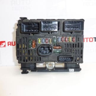
Descrizione
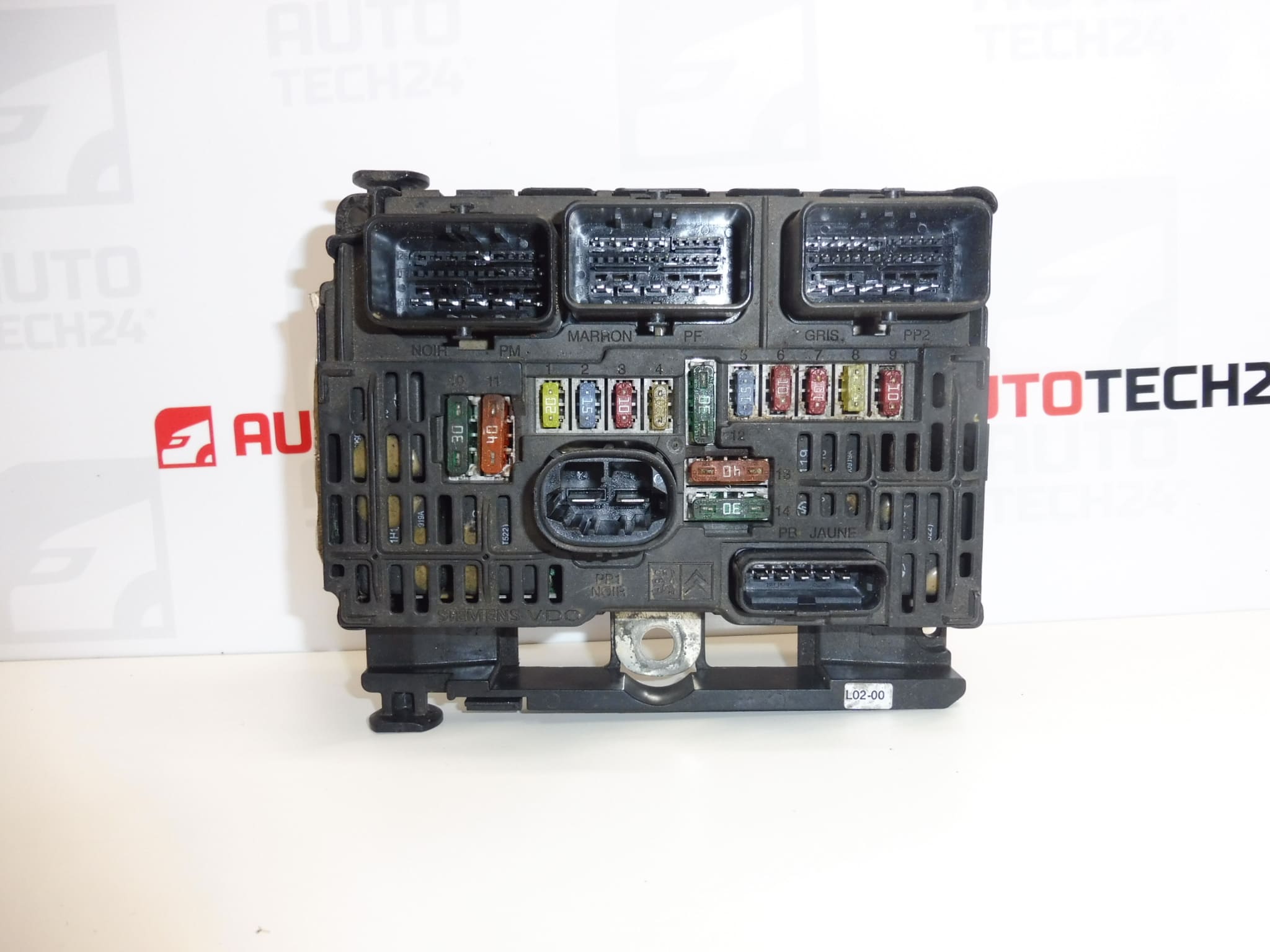
BSM L02-00 SIEMENS VDO for CITROËN and PEUGEOT vehicles
One of the mounting brackets may be damaged; this does not affect functionality
It is from a PEUGEOT 407
Part description
BSM L02-00 Siemens VDO is a used electrical module for Citroën and Peugeot vehicles; the unit offered comes from a Peugeot 407. A BSM generally serves to protect and distribute power to electrical circuits and to switch selected components. It is not a BSI unit or an injection control unit.
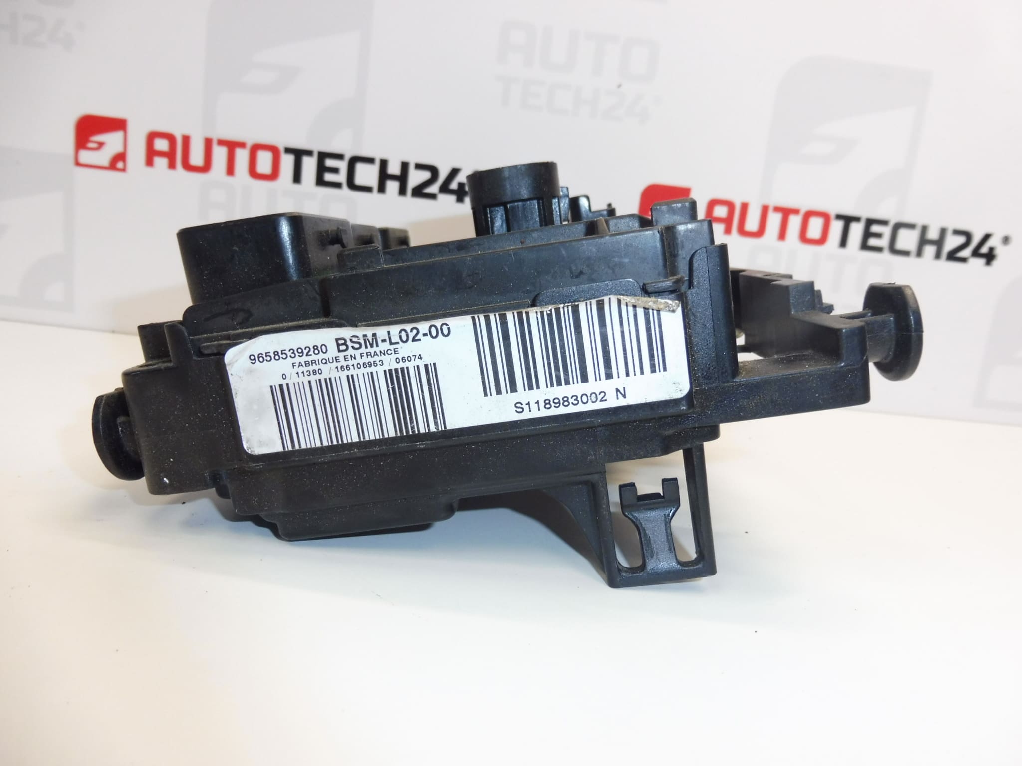
When searching for a replacement part, the L02-00 designation and product numbers 9658539280, S118983002N and 6500CG are essential. Comparing these with the original module and the vehicle documentation helps prevent mix-ups with other BSM versions. A used part is a reasonably priced repair option if it matches the required version.
This unit is noted as possibly having a damaged mounting bracket, which does not affect functionality. Before installation, pay particular attention to the condition of the mounting points and whether the module can be securely fastened.
Technical information
- Manufacturer: SIEMENS VDO
- Model: Peugeot 407
- Part type: BSM electrical module
- Version designation: L02-00
- Vehicle makes listed in the source information: Citroën, Peugeot
- Condition: used part; one of the mounting brackets may be damaged
- Additional number: 6500CG
- Model years and engine types: not specified
Product codes
- Product codes: 9658539280, S118983002N, 6500CG
- Module designation: BSM L02-00
- Model shown on the labels: Peugeot 407
When selecting a part, compare the complete designations, connector configuration and mounting points with the original part. Matching the vehicle make or model alone is not enough to determine whether a particular variant is suitable.
Installation recommendations
The following procedure is general and typically applies to replacing a BSM electrical module. Exact access to the part, the method for disconnecting the power supply, and commissioning requirements depend on the specific vehicle model and configuration. Follow the manufacturer’s service procedure.
1) Before installation
- Compare the product numbers, L02-00 designation, connector shapes, their mechanical keying and mounting points with the old module.
- Inspect the housing, contacts, fuse positions and connector locks. Look for cracks, oxidation, signs of moisture, overheating or scorching.
- Check the mounting brackets in particular. If their condition does not allow the module to be securely fastened, do not proceed with installation until the mounting has been professionally addressed.
- Verify the cause of the original fault. Damaged wiring, a short circuit or water ingress may also damage the replacement module.
2) Tools and materials required
- Standard hand tools appropriate for the fasteners used, and tools for carefully releasing connector locks.
- Lighting, protective gloves, materials for labeling connectors, and a camera to record the connections.
- If necessary, a suitable electrical contact cleaner, a measuring instrument and diagnostic equipment compatible with the vehicle.
3) Step-by-step installation procedure
- Park the vehicle safely, switch off the ignition and all electrical consumers, and secure it against being started unintentionally.
- Follow the manufacturer’s procedure for allowing the electronics to enter sleep mode, then disconnect the battery as specified.
- Gain access to the module according to the service documentation. Clean the surrounding area so that dirt cannot enter the connectors while you work.
- Photograph the original connections and label any connections that could be mixed up during installation.
- Release the connector locks one at a time and disconnect the connectors. Do not pull on the wires or force the locks past their resistance.
- Release the fasteners and remove the original module without putting strain on the surrounding wiring harnesses.
- Inspect the wiring and connectors to be connected. Have any moisture, corrosion or heat damage professionally rectified before connecting the replacement part.
- Compare the two modules again. Check the fuse configuration against the documentation for the specific vehicle; do not automatically transfer the fuses from the donor vehicle.
- Fit the replacement BSM into its designated mount and check that it is stable. The wiring must not support the module or be under tension.
- Connect the connectors to the corresponding sockets and secure their locks. Check that no contacts are pushed back and that no wires are pinched.
- Refit the protective covers, reconnect the battery according to the manufacturer’s procedure, and carry out the prescribed commissioning of the electrical system.
4) Post-installation checks and functional verification
Check that the module is securely mounted, the connectors are locked and the covers are properly closed. Check the operation of the affected electrical circuits according to the vehicle’s equipment, and perform diagnostics if necessary. Watch for any intermittent failures, a smell of overheating or other unusual symptoms. Take a short test drive only after successfully completing the stationary checks and confirming that the vehicle is safe to operate.
5) Common installation mistakes and how to avoid them
- Choosing the wrong BSM variant: compare the complete codes and configuration, not just the appearance or vehicle make.
- Disconnecting while powered: follow the procedure for putting the electronics to sleep and disconnecting the battery.
- Damaging connector locks: first determine how to release them; do not use excessive force.
- Leaving faulty wiring or water ingress unaddressed: remedy the cause of the original fault before installation.
- Insufficient fastening due to a damaged bracket: verify that the module is securely mounted; a loose module can put strain on the connectors and wires.
- Incorrect fuse configuration: follow the vehicle documentation rather than guessing.
Reasons why the part may become damaged
The following factors can generally contribute to damage to BSM modules. These are not confirmed faults with the unit offered.
- Moisture and water ingress, leading to corrosion of contacts and damage to electrical connections.
- A short circuit or overload in a connected circuit, which may cause heat damage.
- Loose or oxidized contacts, increasing contact resistance and causing the connection to heat up.
- Voltage spikes and incorrect work on the electrical system, for example, due to improper handling of the power supply.
- Vibration, material aging and mechanical stress, which can damage the brackets, housing or connector locks.
- Careless removal, particularly prying at the fasteners and pulling on the wiring harnesses.