Descrizione
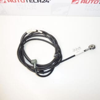
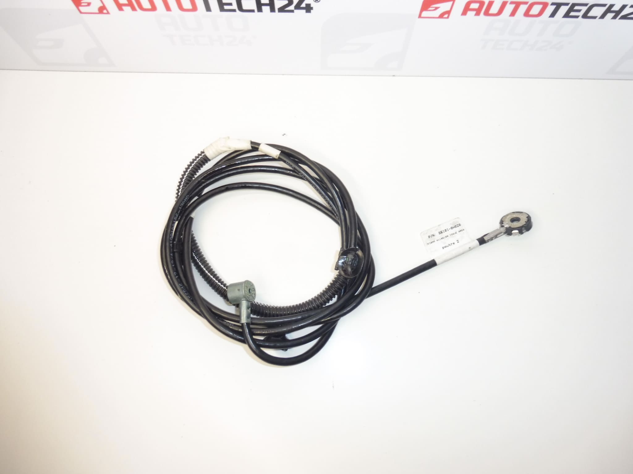
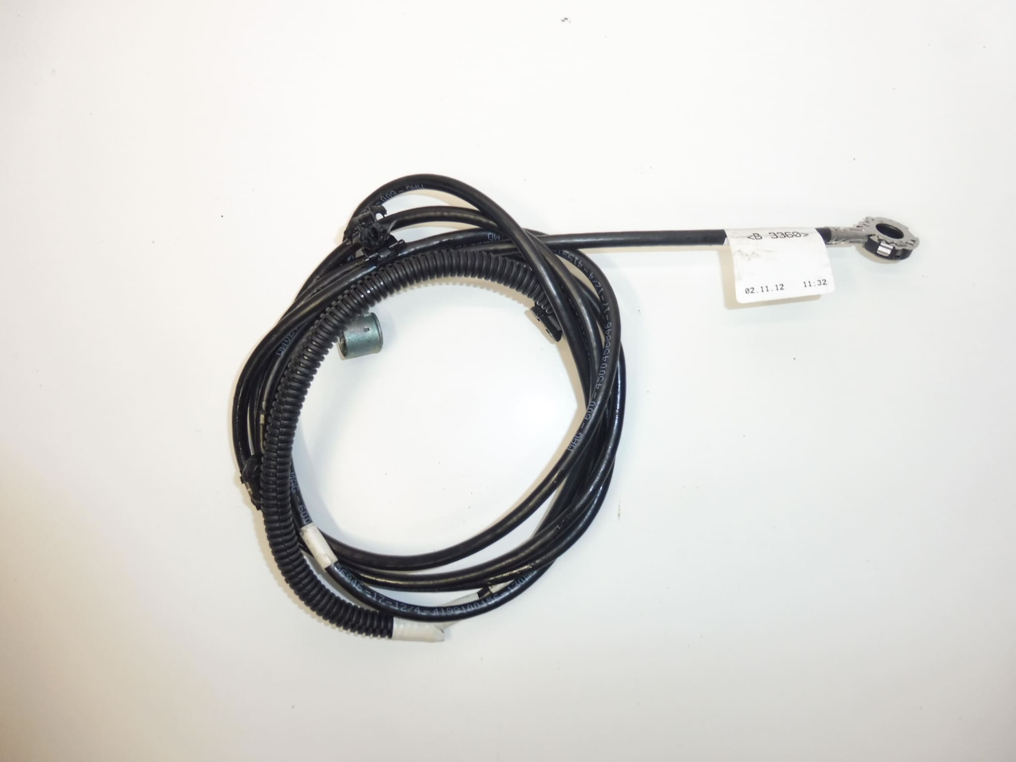
Antenna wiring harness for Citroen C1, Peugeot 107 and TOYOTA Aygo
Part description
The used Citroen C1 / Peugeot 107 / TOYOTA Aygo antenna wiring harness is designed to connect the vehicle’s antenna system. When repairing damaged antenna wiring, it allows you to replace the original harness without improvised connections that can impair radio reception. The identifiers 86101-0H020 and B000699880 are important when looking up the part.
Replacing the antenna harness makes sense especially if the wiring is broken, the insulation is damaged or the connectors are faulty. However, poor reception may have another cause, so it is advisable to also check the antenna and car radio connection before replacing the harness. Before ordering, compare the identifiers, connectors and design with the harness removed from the vehicle.
Technical information
- Manufacturer: not specified; the documentation lists the identifier Stellantis CITROEN PEUGEOT.
- Model: Citroen C1, Peugeot 107 and TOYOTA Aygo according to the long description.
- Models in the labels: PEUGEOT 3008 I | PEUGEOT 5008 I. The labels do not match the long description and do not confirm compatibility with these models.
- Part type: antenna wiring harness.
- Condition: used auto part.
- Additional numbers: not specified.
- Additional identifier from the documentation: NFP.
Product codes
- Product codes: 86101-0H020, B000699880.
When selecting a replacement, refer to the identifier on the original part and also compare the physical design of the harness. Similar-looking connectors alone do not guarantee a suitable replacement.
Installation recommendations
The following applies in general to this type of part: the procedure below describes replacing the antenna wiring. The exact routing of the harness, access to the connectors and removal of the trim depend on the specific model and vehicle configuration.
1) Before installation
- Compare the codes, length, branching, connectors and attachment points with the original harness.
- Inspect the insulation, contacts, connector locks and any shielding. Do not install a harness with exposed wires, pronounced kinks or damaged contacts.
- Investigate the cause of the fault to ensure the new harness is not exposed to the same damage.
2) Tools and materials required
Common hand tools appropriate for the fasteners used, a plastic trim removal tool, a flashlight and suitable cable fasteners are typically useful. For electrical measurements, use an appropriate measuring instrument and follow the vehicle wiring diagram; do not insert unsuitable test probes into the contacts.
3) Step-by-step installation procedure
- Turn off the car radio and ignition. Before working on the electrical system, follow the manufacturer’s procedure for safely disconnecting the battery.
- Access the wiring and its connectors according to the service procedure for the specific vehicle. Release the trim without forcing it.
- Take photos of the original harness routing, its attachments and the orientation of the connectors.
- Release the connector locks and disconnect them by pulling on their housings, not on the cable.
- Gradually remove the wiring from the clips and holders. Do not interfere with nearby wiring or safety systems.
- Compare the removed harness with the replacement part again, especially the end fittings and the length of each section.
- Check the wiring route and eliminate any causes of abrasion, pinching or exposure to moisture.
- Route the replacement harness along the original path. Keep bends gradual and ensure there is no tension near the connectors.
- Connect the connectors and check that they are locked in place. Restore the fastenings so the cable is neither pinched nor left loose where it could obstruct anything.
- Restore the power supply according to the manufacturer’s procedure and check that the radio works. Then complete the trim installation and check that its edges are not trapping the wiring.
4) Post-installation checks and function testing
Test reception of several radio stations and watch for any dropouts or interference. Compare the results under similar reception conditions. During a short test drive, check whether the fault occurs under vibration; the radio must not distract the driver while driving.
5) Most common installation errors and how to avoid them
- Pulling on the cable: disconnect connectors only after releasing their locks, and hold them by their housings.
- Sharp bends and pinching: follow the original route and check the positioning before refitting the trim.
- Connectors not fully engaged: check that every connection is locked without using excessive force.
- Replacing without diagnosing the cause: first rule out a fault with the antenna, car radio or their connection.
Reasons why the part gets damaged
Antenna harnesses are generally damaged mainly by mechanical stress and exposure to moisture. Typical causes include:
- Wiring pinched during installation of trim or other components.
- Insulation rubbing against edges and loose cable fastenings.
- Sharp bending or pulling on the cable during removal.
- Moisture and subsequent corrosion of the contacts.
- Improper modifications, unsuitable connections or damage to the shielding, if it is part of the wiring.