Descrizione
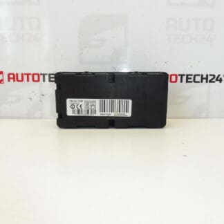
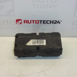
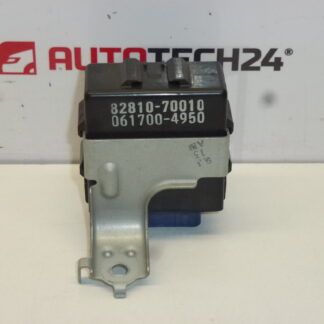
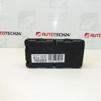
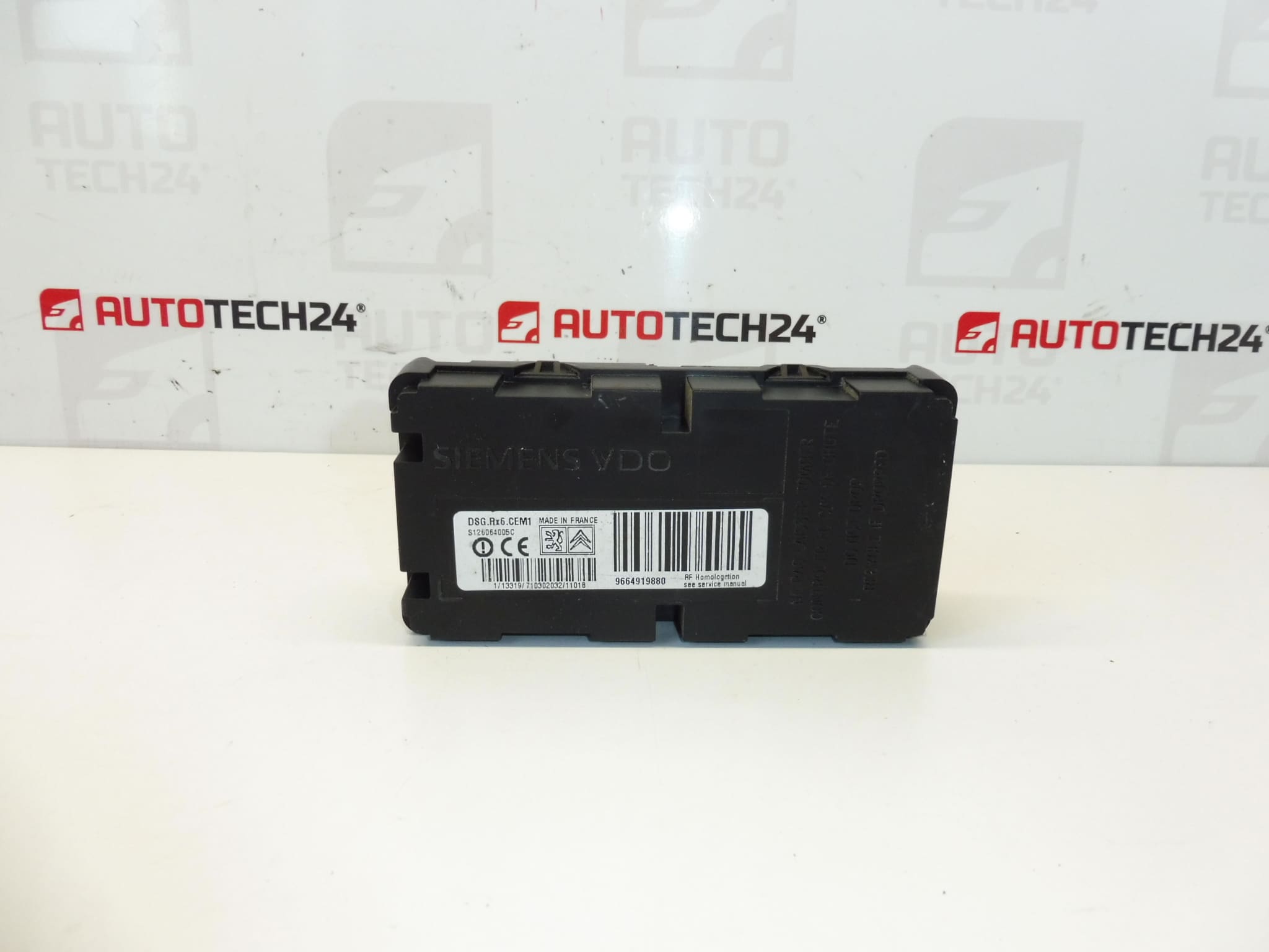
Tire pressure monitoring control unit for C5 X7 vehicles
Part description
The used tire pressure monitoring control unit for Citroen C5 X7 is part of the underinflation monitoring system. This system helps alert the driver to a drop in tire pressure. Replacing the unit may be a solution if the original part has been confirmed faulty; however, an underinflation warning alone does not mean that the control unit itself is faulty.
When selecting a replacement part, compare the markings 9664919880, S126064005C and 5430N0 in particular with the original part. A used part offers a repair option without purchasing a new unit, provided it matches the system specification required for your vehicle.
Technical information
- Manufacturer: not specified
- Model: Citroen C5 X7
- Part type: tire pressure monitoring control unit
- Condition: used part
- Additional numbers: 9664919880, S126064005C, 5430N0
- Category: electrical components – control units
Product codes
- Product codes: 9664919880, S126064005C, 5430N0
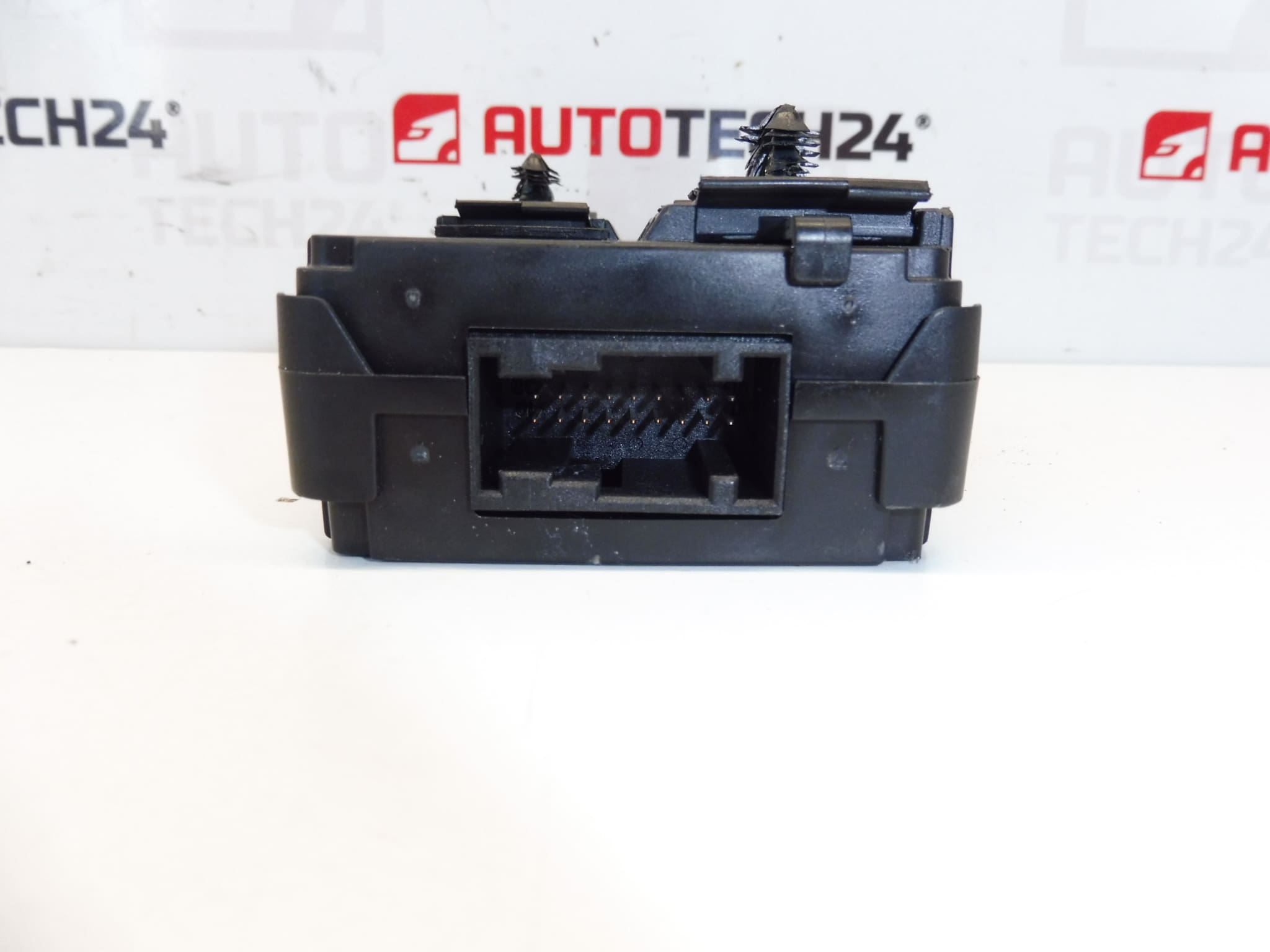
The codes listed are used to identify the part. In addition to the markings, also compare the connectors and the design of the original unit; matching the vehicle model alone is not sufficient to select the part.
Installation recommendations
The following procedure is general for this type of electronic part. The exact steps for removal, connection and any necessary setup depend on the specific vehicle configuration and the manufacturer’s instructions. The available information does not specify configuration requirements for this unit, so immediate operation after connection alone cannot be assumed.
1) Before installation
- First, use diagnostics to verify the cause of the fault. In general, problems with the tire pressure monitoring system can also be caused by a sensor, power supply, wiring or connector.
- Compare the product numbers, housing shape, mounting points and connectors with the removed part.
- Check the used unit for cracks, damaged contacts, corrosion and signs of moisture. If any damage is found, do not connect the unit without having it professionally assessed.
- If possible, record the diagnostic data and any available settings of the original unit before removal.
2) Tools and materials required
- Standard hand tools suitable for the fasteners used.
- Tools for carefully releasing covers and connector locks, if required.
- A diagnostic tool that supports the vehicle’s relevant system.
- Good lighting, a clean cloth and, if necessary, a product suitable for electrical contacts.
3) Step-by-step installation procedure
- Park the vehicle safely, secure it against movement and switch off the ignition.
- Following the manufacturer’s service instructions, allow the electronic systems to enter their quiescent state and disconnect the battery using the prescribed procedure.
- Access the unit according to the service documentation for the specific vehicle. Release covers and fasteners without using excessive force.
- Before disconnecting anything, note the wiring routing, connector orientation and how the unit is secured.
- Release the connector locks and disconnect the connectors by holding their housings, not by pulling on the wires.
- Undo the fasteners and remove the original unit. Check the surrounding area for moisture, dirt or damaged wiring.
- Compare the original and replacement parts again. Remove any cause of damage, such as water ingress, before installing the replacement.
- Secure the replacement unit as specified by the manufacturer. The housing and brackets must not be subjected to deformation.
- Connect the connectors and check that their locks are engaged. Route the wiring so that it is not pinched, under tension or in contact with sharp edges.
- Reinstall the removed covers, reconnect the battery according to the manufacturer’s instructions and perform a diagnostic check. Carry out any setup or initialization only in accordance with the procedure for the specific system configuration.
4) Post-installation checks and function verification
- Verify communication with the unit and assess any faults stored in the diagnostic system.
- Check the actual tire pressures against the specified values for the vehicle. Do not deal with an underinflation warning merely by clearing the alert.
- If the service procedure requires a road test, perform it only after checking that the vehicle and tires are safe.
- After verifying operation, check the system warnings and diagnostics again. If problems persist, the entire system must be checked; this does not automatically mean that the unit should be replaced again.
5) Common installation mistakes and how to avoid them
- Replacing the unit without identifying the cause: first check the sensors, power supply and associated wiring.
- Selecting a part based only on the vehicle model: also compare the markings and part specification.
- Disconnecting while the electronics are active: follow the manufacturer’s procedure for shutting down the systems and disconnecting the battery.
- Damaging connectors: release the locks first and never pull on the wires.
- Leaving moisture or corrosion in place: eliminate the source of the problem, otherwise the fault may recur.
- Skipping the final diagnostic check: after replacement, verify communication and whether system setup is required.
Reasons why the part may be damaged
The following are general factors that may cause damage to electronic units of this type. They do not describe the condition found in the item offered for sale.
- Moisture and water ingress, which may cause contact corrosion or damage to the electronics.
- Electrical overload, short circuit or overvoltage in associated circuits.
- Mechanical stress, impact, housing damage or improper handling during removal.
- Damaged connectors and wiring, which may cause intermittent operation and mimic a fault in the unit itself.
- Aging electronic components due to prolonged exposure to temperature changes and vibration.