Descrizione
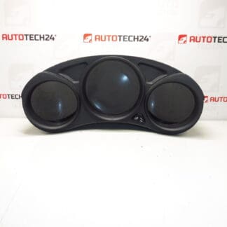
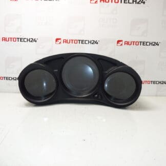
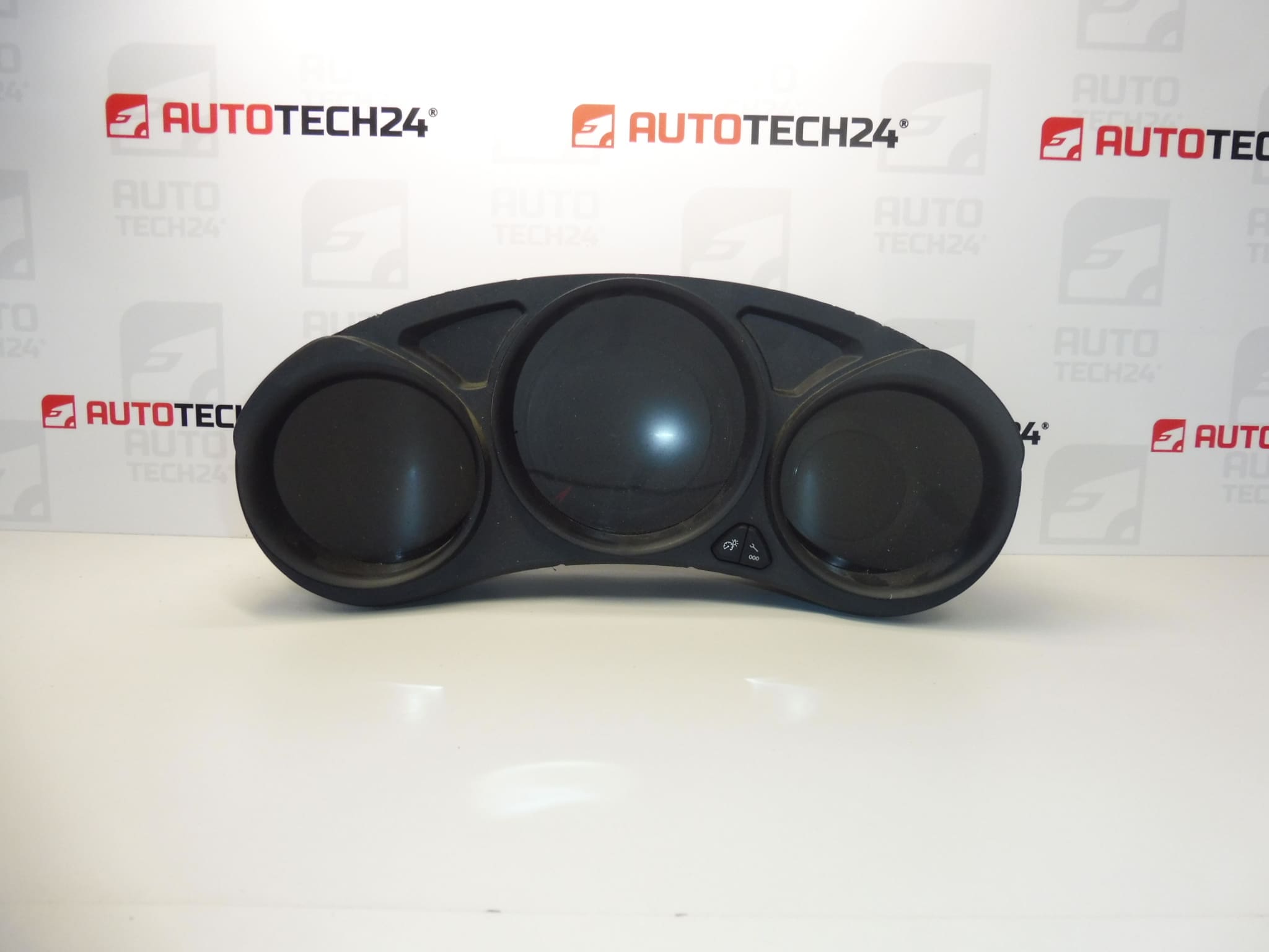
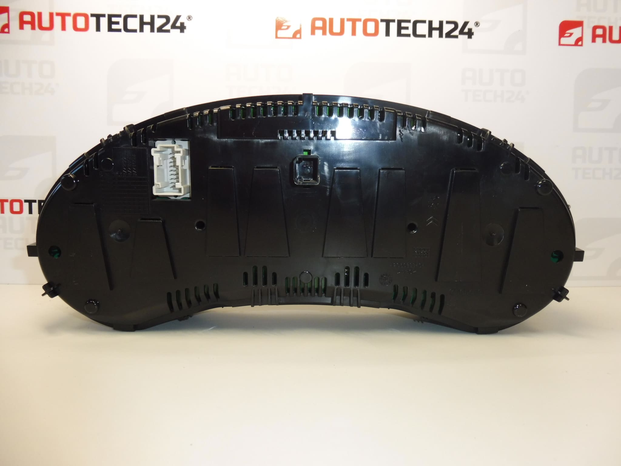
Instrument cluster for CITROEN C4 B7 vehicles
Mileage is unknown
Part description
Used speedometer – instrument cluster for Citroen C4 II B7 is intended as a replacement part when replacing the original instrument panel. An instrument cluster generally displays speed, operating information and warning lights important to the driver. When selecting a replacement, compare in particular the markings 9676962980 and 9813297080 with the original part, as well as the connectors, mounting points and panel design.
This is an option for replacing a damaged instrument with a used part. The stored mileage reading is not available; before replacement, it is therefore also important to assess how the mileage reading is handled for the specific vehicle.
Technical information
- Manufacturer: not specified; the source materials list the designation Stellantis CITROEN PEUGEOT.
- Model: Citroen C4 II; B7 version according to the title and long description.
- Part type: instrument cluster / speedometer.
- Condition: used part.
- Mileage: unknown.
- Other numbers: not specified.
Product codes
- Product codes: 9676962980, 9813297080.
- Model: Citroen C4 II.
Product numbers are an important reference when looking for a replacement. The source materials do not clarify the differences between the listed numbers or the instrument’s configuration requirements, so it cannot be assumed that all versions are fully interchangeable.
Installation recommendations
The following procedure generally applies to this type of part. The precise removal, electrical disconnection and any required setup depend on the specific model and vehicle version. The source materials do not state whether this unit requires configuration or how the mileage reading is handled when it is connected.
1) Before installation
- Compare the numbers on the original and replacement instruments, the shape of the cover, mounting points, connectors and display design.
- Check the cover, display, mounting components and contacts. Look for cracks, signs of moisture, corrosion or bent pins.
- If the condition of the original panel allows, record the mileage displayed and the symptoms of the fault.
- Before connecting it for the first time, check the service documentation for the mileage synchronisation procedure. In some vehicles, connecting a used instrument to the vehicle’s electronics may change the displayed reading. The stored mileage for this unit is unknown.
- Check whether the fault may be due to the power supply, wiring or connections rather than the instrument itself.
2) Tools and materials required
- Tools appropriate for the fasteners used.
- Plastic trim removal tools for carefully releasing the trim.
- A flashlight, a soft protective surface and a container for removed fasteners.
- If needed, a suitable measuring instrument and diagnostic equipment compatible with the vehicle.
3) Step-by-step installation procedure
- Park the vehicle safely, secure it against movement and switch off electrical accessories.
- If possible, record the operation of the original instrument, the mileage reading and any diagnostic findings.
- Before connecting the replacement unit, clarify the configuration requirements and how the mileage reading is handled. If these are unclear, postpone the connection.
- Switch off the ignition and allow the electronics to enter sleep mode according to the manufacturer’s procedure. Then disconnect the battery as instructed.
- Following the service documentation, remove the trim needed to access the instrument. Do not force the plastic clips.
- Release the original instrument’s fasteners and carefully pull it out far enough to avoid straining the wiring.
- Release the connector locks and disconnect them by pulling on the connector housing, not the wires.
- Compare the two parts side by side and check the condition of the sockets and wiring harness. Repair any damaged connections before installation.
- Connect the replacement instrument and secure the connectors. Fit the unit without force and without trapping any wires.
- Fasten the instrument and reinstall the trim according to the manufacturer’s procedure. Do not overtighten the fasteners.
- Restore the power supply according to the service procedure. If configuration is required for this version, carry it out using suitable diagnostic equipment.
- Check the display, warning lights, backlighting and mileage reading. Record the replacement and the readings noted in the vehicle’s service documentation.
4) Post-installation checks and function verification
Check that the display is legible, the backlighting is stable, and the gauges and warning lights respond as expected for the vehicle’s equipment. Make sure the panel does not come loose and that the trim is secured properly. If the instrument is working correctly and there are no warnings that would make driving unsafe, take a short test drive and monitor the speed display and any other available readings. Address any mileage discrepancies professionally and transparently.
5) Most common installation errors and how to avoid them
- Connecting the unit without assessing the mileage reading: first find out the rules for storing and synchronising it for the specific vehicle.
- Selecting a part based on appearance alone: compare the markings, connectors and instrument design.
- Disconnecting while powered: follow the manufacturer’s procedure for putting the electronics to sleep and disconnecting the battery.
- Damaging clips or contacts: use appropriate tools and always release the connector locks first.
- Connectors not fully engaged or wiring pinched: check that the connectors are secured and the wires are routed correctly before refitting the trim.
- Replacing the part without identifying the cause of the fault: also check the power supply and electrical connections to prevent the problem from recurring.
Reasons why the part may become damaged
The following causes of damage or failure may generally occur with instrument clusters. This is not a description of the condition found on this unit.
- Ageing electronics and thermal stress, which may lead to display or backlight failures.
- Moisture and corrosion that damage contacts and electronic circuits.
- Unstable power supply or overvoltage, which may place stress on the instrument’s electronics.
- Vibration and loose connections that cause intermittent operation.
- Careless removal, which may crack the brackets, cover or connector locks.
- Unsuitable cleaning, particularly liquid ingress or damage to the transparent cover from an aggressive cleaning agent.