Descrizione
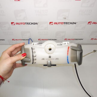
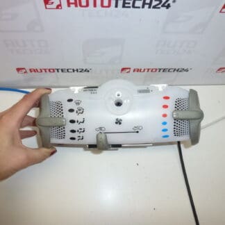
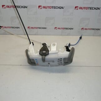
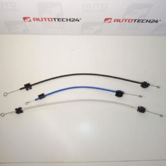
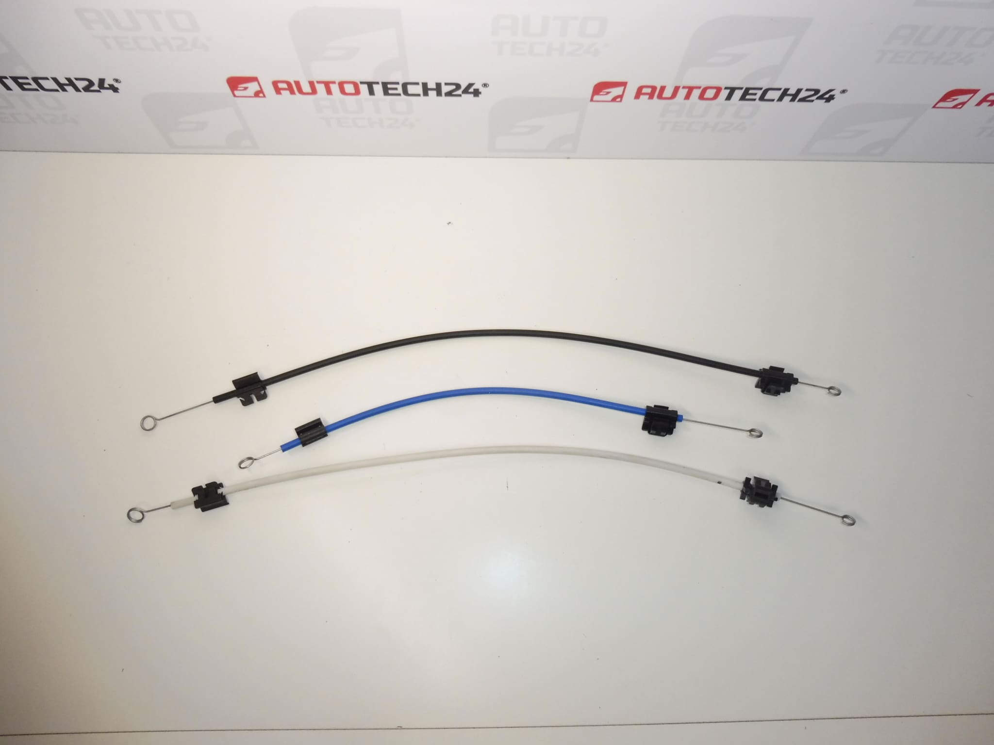
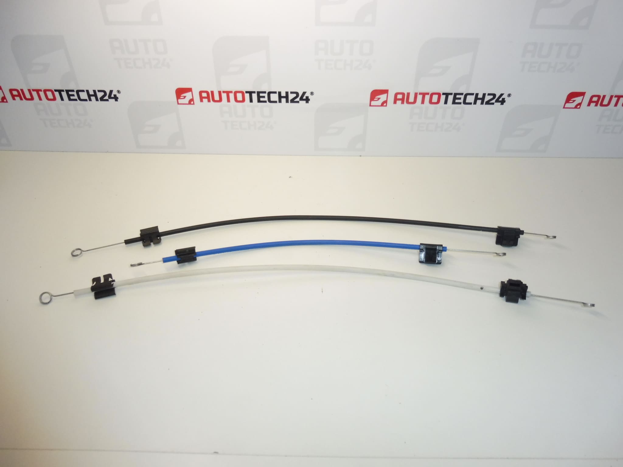
Heater and manual air conditioning control cable set for CITROEN C1 and PEUGEOT 107 vehicles up to 2014
Part description
Used heater and manual air conditioning control cable set for Citroën C1 and Peugeot 107 transfers movement mechanically from the controls to the relevant heating and ventilation mechanisms. It is a suitable choice when repairing controls that do not respond correctly, have excessive play, or stick due to a damaged cable or its attachment.
When selecting the part, compare in particular the product numbers 6451SG, 6451SJ and 6451SH and the design of the original cables. It is specified for vehicles up to 2014 with manual air conditioning; do not automatically substitute it for parts designed for a different control system.
Technical information
- Manufacturer: not specified; the source materials list the designation Stellantis / CITROEN / PEUGEOT.
- Model: Citroën C1, Peugeot 107.
- Part type: heater and manual air conditioning control cable set.
- Year range: up to 2014 according to the source materials.
- Condition: used part.
- Additional numbers: not specified.
Product codes
- Product codes: 6451SG, 6451SJ, 6451SH.
- Models: Citroën C1, Peugeot 107.
Installation recommendations
The following procedure generally applies to this type of mechanical control cable. The exact access to the controls, method for releasing the clips, and any adjustment required depend on the specific model and vehicle configuration. Follow the manufacturer’s service procedure.
1) Before installation
- Compare the part numbers, cable length and shape, end fittings, and attachments with the removed parts.
- Check that the used cables are not deformed, the ends are not cracked, and any sheaths or Bowden cables are not damaged.
- Check that the cables move smoothly without force. Also check that the controlled mechanism moves freely to ensure that the original fault does not damage the newly installed parts.
- Before removal, take photos of the cable routing, which cable connects where, and the position of the clips.
2) Tools and materials required
- Standard hand tools suitable for the fasteners used.
- Plastic trim removal tools and suitable pliers for working with clips.
- A flashlight, cleaning cloth, and materials for marking individual cables.
3) Step-by-step installation procedure
- Park the vehicle safely, secure it against movement, and switch off the ignition.
- If access requires disconnecting electrical connectors, disconnect the battery in accordance with the vehicle manufacturer’s instructions.
- Following the service procedure, gain access to the controls and cable attachments. Remove the trim carefully without levering it by force.
- Record the position of the controls and controlled mechanisms. Mark the individual cables to avoid mixing them up.
- Carefully release the retainers and ends of the original cables. Do not pull on a cable until its attachment has been fully released.
- Remove the original cables from their routing and compare them with the replacement set. Also check the condition of the attachments on the control and controlled mechanism.
- Check that the mechanisms move freely without applying force. If any mechanism sticks, first eliminate the cause of the resistance.
- Route the replacement cables in the same way as the originals, without sharp bends, twisting, or tension. If they have Bowden cable sheaths, seat them correctly in their brackets.
- Connect the ends and secure all clips. If the design allows for adjustment, make the adjustment according to the service procedure for that configuration.
- Before refitting the trim, slowly test the full range of control movement. Check that the cables do not pop out or rub, and that the relevant positions can be reached without excessive resistance.
- Refit the removed parts, reconnect any electrical connections according to the manufacturer’s procedure, and carry out a final function check.
4) Post-installation checks and function verification
With the vehicle stationary, test the relevant control positions and check that the heating and ventilation respond accordingly. Check for smooth operation, secure attachment, and absence of unusual noises. Assess the effect of temperature changes only under appropriate operating conditions. Carry out a test drive only after the interior has been fully reassembled; the controls must not distract the driver.
5) Common installation errors and how to avoid them
- Mixing up the cables: mark their function and routing before removal.
- An end fitting or sheath that is not secured properly: check all attachments while moving the control before refitting the trim.
- A sharp bend or pinching during trim installation: follow the original routing and check operation again after assembly.
- Forcing the control past resistance: if it sticks, stop testing and check the routing and controlled mechanism.
- Incorrect initial position: when connecting the cables, observe the relative positions of the control and mechanism in accordance with the service procedure.
Reasons why the part gets damaged
With this type of control cable, damage is generally associated with mechanical strain and increasing resistance in the controlled mechanisms. This is not a description of defects in the specific set offered for sale.
- Wear to the ends and attachments from repeated use of the controls.
- Aging of plastic components, which can cause clips to crack or attachments to lose their grip.
- A seized controlled mechanism and resulting overloading of the cable when the control is turned with excessive force.
- Incorrect cable routing, sharp bends, or pinching following previous work.
- Careless removal, especially pulling on end fittings that are still secured.