Descrizione
Heater servo motor for CITROËN C4 and PEUGEOT 307 II vehicles
Part description
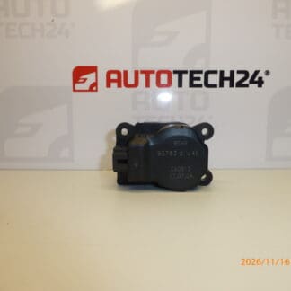
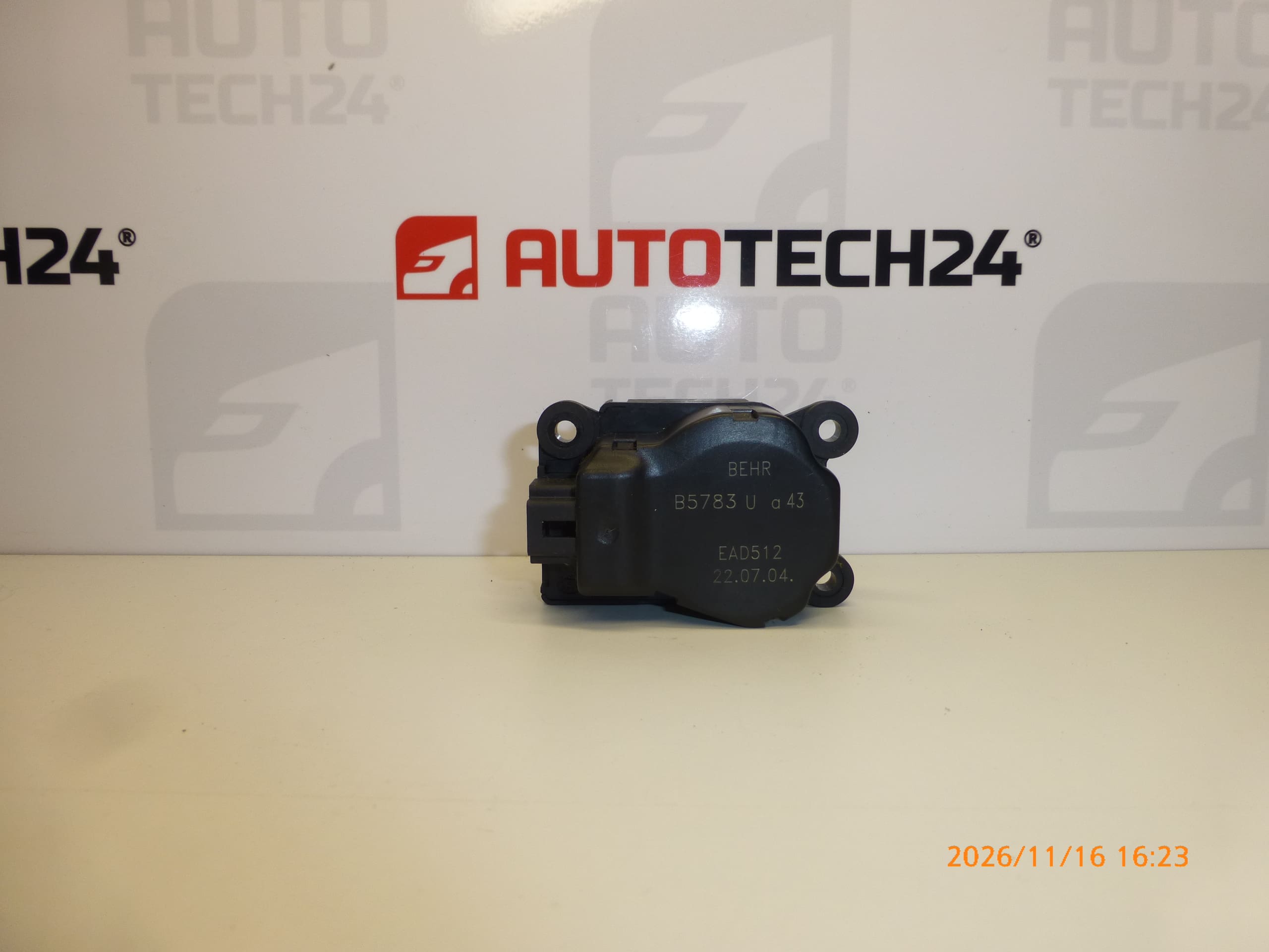
Used BEHR B5783 U and 43 heater servo motor is an electrical actuator in the heating and air conditioning system. Servo motors of this type adjust the air distribution flaps according to the control settings. A faulty actuator may be indicated by clicking, irregular flap movement, or the heater settings failing to produce the expected change.
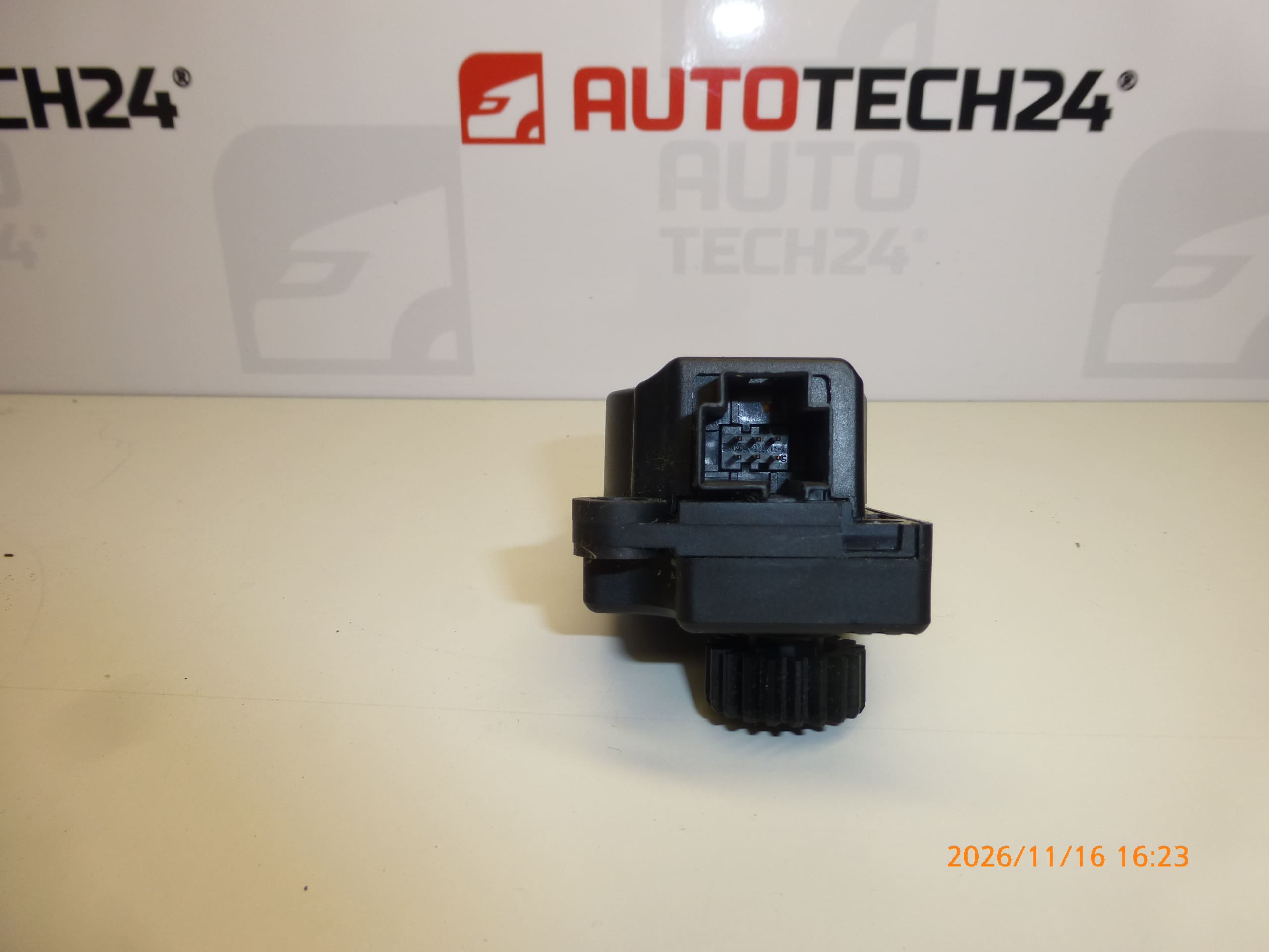
The EAD512, 6447RZ and 6447RF designations are important when searching for a replacement part. Before selecting a part, compare the designation on the original servo motor, the connector, the mounting points and the actuator output design. A correctly selected used part can be a cost-effective repair solution if the fault is caused by the servo motor itself, rather than a jammed flap or an electrical wiring fault.
Technical information
- Manufacturer: BEHR
- Model: Citroën C4 | Peugeot 307; the long description specifies Peugeot 307 II.
- Part type: electric heater servo motor.
- Version designation: B5783 U and 43
- Other numbers: EAD512, 6447RZ, 6447RF
- Condition: used part.
- Specific flap controlled and air conditioning configuration: not specified.
Product codes
- Product codes: 6447RZ, 6447RF, EAD512, B5783 U and 43
- Models listed on labels: Citroën C4 | Peugeot 307
Code 6447RZ is listed in the product name, while 6447RF appears in the short description. The information provided does not confirm that they are interchangeable; therefore, when selecting a part, also refer to the designation and construction of the original part.
Installation recommendations
The following procedure applies in general to this type of part. The exact access to the servo motor, removal of surrounding parts and any end-stop adjustment depend on the specific model and heating or air conditioning configuration.
1) Before installation
- Compare the designations on both parts, the connector shape and number of contacts, the mounting points and the shape of the output coupling.
- Inspect the used part: the housing and mounts must not be cracked, the contacts must not be corroded, and the actuator output must not be visibly damaged.
- Check whether the problem is caused by the wiring, a loose connector or a mechanically jammed flap.
- Before disassembly, take photos of the wiring routing, mounts and position of the original actuator.
2) Tools and materials required
- Screwdrivers or bits suitable for the fasteners used.
- Plastic trim removal tools, a flashlight and a container for fasteners.
- A clean cloth and, if necessary, a product intended for cleaning electrical contacts.
- If needed, suitable automotive diagnostics to check operation and perform any required initialization.
3) Step-by-step installation procedure
- Secure the vehicle against movement, switch off the ignition and follow the manufacturer’s instructions for safely disconnecting electrical components. If the battery must be disconnected, follow the prescribed procedure.
- Access the faulty servo motor according to the service procedure. Carefully release the surrounding covers to avoid damaging their clips.
- Note the position of the actuator and how it connects to the flap mechanism.
- Release the connector lock and disconnect it by holding the connector body, not by pulling on the wires. Check the condition of the contacts and wiring.
- Release the servo motor mounts and carefully separate it from the mechanism it controls. Do not pry against the plastic mounts.
- Check the connection to the flap and, according to the service procedure, verify that it moves freely. Do not force the mechanism past its end stops.
- Compare the removed part with the replacement again. If the connector, mounting points or output coupling differ, do not proceed with installation.
- Fit the replacement servo motor so that its output engages correctly with the flap mechanism. Align it according to the service instructions; do not force the gears to turn and do not tighten the screws if the part is not seated correctly.
- Secure the servo motor according to the manufacturer’s instructions, connect the connector and route the wiring away from moving parts and sharp edges.
- Restore power using the prescribed procedure. If this particular configuration requires initialization or end-stop adjustment, carry it out according to the appropriate service procedure.
- Check operation before fully refitting the covers. Then reinstall the removed covers and trim.
4) Post-installation checks and function verification
Gradually change the heating and air conditioning settings related to the actuator being repaired. Check that the system responds and that there is no repeated clicking or gear skipping. Check that the connector and wiring are secure. After reassembly, operation can also be checked during a short test drive; test the controls only when it is safe to do so.
5) Most common installation errors and how to avoid them
- Choosing a part based only on the vehicle model: also compare the designation, connector and mechanical design of the actuator.
- Replacing the part without checking the flap: first eliminate any binding, otherwise the replacement servo motor may be overloaded again.
- Forcing the coupling into place or turning it too far: align it according to the service procedure rather than applying pressure to the part.
- Overtightening fasteners: follow the manufacturer’s instructions and protect the plastic mounts from cracking.
- Skipping the required initialization: find out whether the specific system configuration requires it and perform it if necessary.
Reasons why the part gets damaged
The following are general causes of heater servo motor faults; they do not describe the condition found on this particular unit:
- Gear wear caused by repeated flap adjustments.
- Flap binding or jamming, which puts excessive strain on the actuator and its gears.
- Wear of the electric motor or position sensor, if included in this particular version.
- Moisture and contact corrosion, which can disrupt the electrical connection.
- Damage during careless removal or installation, especially cracked mounts or damage to the output coupling.